DC Drives

Although the majority of variable speed drives on vessels are now AC VFD (variable frequency drives) some DC SCR drives still exist. The common PQ problems encountered are:

Note : The negative effects of harmonics are acknowledged in many technical papers (see Resources section for more information) and do not require any explanation here other than to state that they generally fall into two basic categories:

  • Excessive heating caused by additional I2R losses, iron losses, skin effect (due to VFDs), etc. in cables and equipment (e.g. generators, transformers and motors).
  • Voltage distortion resulting from harmonic currents, at the various frequencies, passing through the system impedances and leakage inductances of the power system, disrupting or destroying susceptible equipment.

Harmonic voltage distortion is essentially ‘pollution’ of the vessel’s supply voltage and is ‘seen’ by all equipment connected to the power system.

Most conventional variable AC VFD and DC speed drives offshore are ‘6 pulse’ (i.e. one three phase rectifier). All rectifiers, when fed with sinusoidal voltages, draw non-sinusoidal or ‘non-linear current’ from the supply hence are termed ‘non-linear loads’. When the supply voltage is distorted and/or imbalanced, uncharacteristic harmonic currents and voltage are also drawn from the supply.

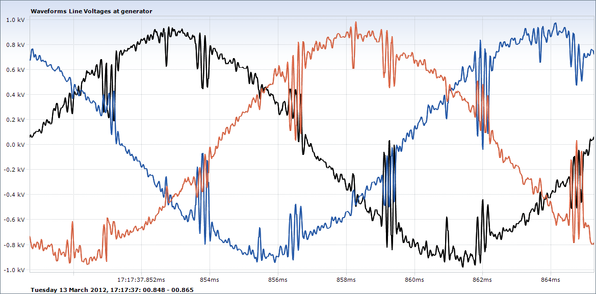
Fig 1 illustrates the voltage distortion despite the load current being relatively sinusoidal. The maximum total harmonic voltage distortion (Uthd) show is 19.2%. The maximum Uthd during the site visit was 26.3%. The high Uthd was due to the switching of the SCRs.

DC drives – Line notching

Due to the commutation process within DC drives, the line voltages are short circuited as one thyristor (SCR) device transfers current to the next device. The depth of voltage notch is exacerbated if there are no AC line reactors in the DC drives as only the inductance of the generators limit the short circuit current.

The result can be spurious zero crossovers (of the voltages) leading to misfiring on equipment which depends on true zero crossovers for timing (e.g. AVRs and SCR firing control boards). Line notching, by interacting with cable and other stray impedances can excite repetitive voltage spikes which disrupt and damage equipment.

Fig 3 shows typical line notching due to three DC drive drives operating at differing control angles (i.e. output DC voltage). Note the primary line notching tends towards zero at low speed, high torque operation (i.e. low DC voltage, high DC current).

Fig 3 : Detailed view of the voltage waveform distortion including line notching at the busbars

Fig 4 depicts the harmonic line voltage spectrum (Uthd) during time period of the waveforms shown in Fig 2.

Fig 4 : Min/max line voltage harmonic spectrum during the period of measurement seen in Fig 2

Note that on this occasion there are three discrete harmonic voltage spectrums (however there will be of course be some frequency overlap, over the three spectrums) :

  1. The 3rd to 24th harmonic due to the non-linear load current drawn by the DC drives acting on the system impedances.
  2. The 32nd to 59th due to the top drive VFD common mode voltage impressed on the switchboard busbars via the ground (hull) connection.  560kW had own generator.
  3. The 65th to 99th due mainly to the high frequency components in the line voltage notches.

Note with conventional power quality analysers only the harmonic voltages to the 50th or 63rd order will only be visible. This restriction does not assist troubleshooting as only portion of the overall PQ picture can be observed. For this reason, we use advanced cycle by cycle power quality analysers which capture every single cycle and harmonic orders to 512st in addition to 200MHz scope-meters with inbuilt spectrum analysers and EMC spectrum analysers).

DC Drives – Voltage Spikes

On ships and other installations with DC drives without AC line reactors, the interaction between the line notching and stray cable and other capacitance (e.g. VFD EMC filters) can result in ringing (i.e. voltage oscillations) and resonance within the line notches (Fig 5) and repetitive voltage spikes (Fig 6).

The effects of the voltage spikes can be serious and very disruptive. On one vessel, for example, the following failures, recorded over a five month period, were attributed directly to repetitive voltage spikes :

  • Four VFD EMC filters totally destroyed
  • Multiple failures (>10 off) 24V and 48V switched mode power supplies
  • Multiple failures (>12 off) electronic thermostats
  • Numerous failures of fire & gas detection system input filters
  • Repeated and multiple failures of fluorescent lighting capacitors
  • Continual tripping of laundry washing machines (which contained small VFDs)

DC Drives – Low generator displacement power factor

For DC drives, the displacement power factor (DPF – fundamental components) and true power factor (TPF), which includes the harmonic components, are similar in value.  Both are dependent on the drive output DC voltage (DC motor speed) and torque demand (DC current). At low speed/high torque operation, the generators have to supply significant amounts of reactive power (kVAr) to the DC drives, reducing the generator power factor significantly and, depending on the DC drive rating, possibly limiting the generators capability to supply the design kW load without overheating.

Fig 7 shows the relationship between L12 voltage and L1 current at low displacement power factor.

Fig 8 illustrates the rms current, power factor and reactive power demand (kVAr) for the DC drive on a dynamic load. As can be seen, the power factor reduces (and kVAr demand increases) during periods of increased current demand. The power factor and reactive power demand are dynamic and also dependent on the number of generators operating in parallel.

Note : VFDs have a high ‘displacement power factor’ (DPF), around 0.96-0.97 lagging, irrespective of load. With VFDs the ‘true power factor’ (TPF), which includes the ‘harmonic distortion factor’ always is lower and is dependent on the harmonic current magnitude.

This high VFD (or common DC bus system) DPF can lead to problems with generator leading power factor if some types of passive harmonic mitigation are used as they can inject reactive power into the power system at light or no load unless precautions are taken.

To return to common power quality issues please click here.