Capacitor-based low voltage (LV) contactor and SCR switched power factor correction (PFC) systems have been employed for correcting displacement power factor for around the past 60 years. In that time, there has many improvements in capacitor and switching designs. When correctly designed, these PFC systems can be reliable and rugged. However, there are many capacitor-based systems installed which struggle technically with harmonics, leading displacement power factor, system response time, and temperature challenges. While most of the challenges can be overcome with the correct design, correct component selection and superior quality manufacture, there are alternate technologies now available.
Conventional capacitor systems are available with SCR (i.e.) thyristor switches instead of conventional contactors. This can make them a fast-acting solution, operating within 30 milliseconds, still not as fast as an SVG, but fast enough for most applications but failed to address both leading and lagging DPF.
Over the last 10 years, static VAR compensators or ‘static VAR generators’ (SVGs) have become available for LV applications and are now seriously challenging conventional power factor correction equipment. SVGs are simple in concept but do require significant expertise in electronic design due to an assortment of individual components. Their flexibility is excellent, and there is no doubt that as electronics become simpler and more reliable, these systems will eventually seriously challenge conventional PFC systems.
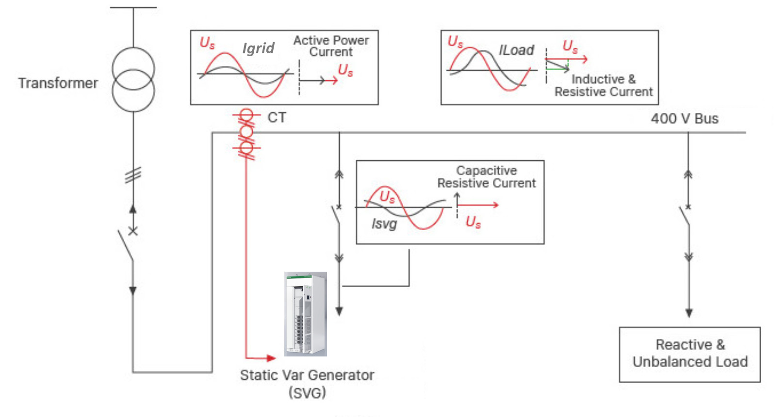
The basic principle of an SVG is illustrated above. The SVG operates by detecting the load current in real time via external CTs and thus determines the reactive components of the load. The data is analysed by the SVG control system which adjusts the triggering of the PWM of the IGBTs (or SiC) device firing such that the SVG inverter produces the exact reverse reactive current of the corresponding load current reactive content. The resultant current is injected into the grid to compensate for the reactive content of the load current. By controlling the SVG output voltage amplitude and phase angle, or directly controlling the AC current, the SVG can absorb leading VAR or generate lagging VAR according to the load reactive power or grid voltage level.
Ultra SiC SVGs
Ultra SiC SVGs are very similar to their SiC active filters counterparts.. Both are modular in construction and of identical physical sizes. Ultra SiC can combine both harmonic mitigation (AHF) and reactive power control (SVG) in one enclosure or modular system.
Ultra SiC SVGs are available currently up to 480V in various kVAr ratings which can be paralleled up to the desired rating.
Ultra SiC SVGs and active filters can be combined as modules or in enclosures, connected to PCC (i.e. point of common coupling) thus providing harmonic mitigation and reactive power control.
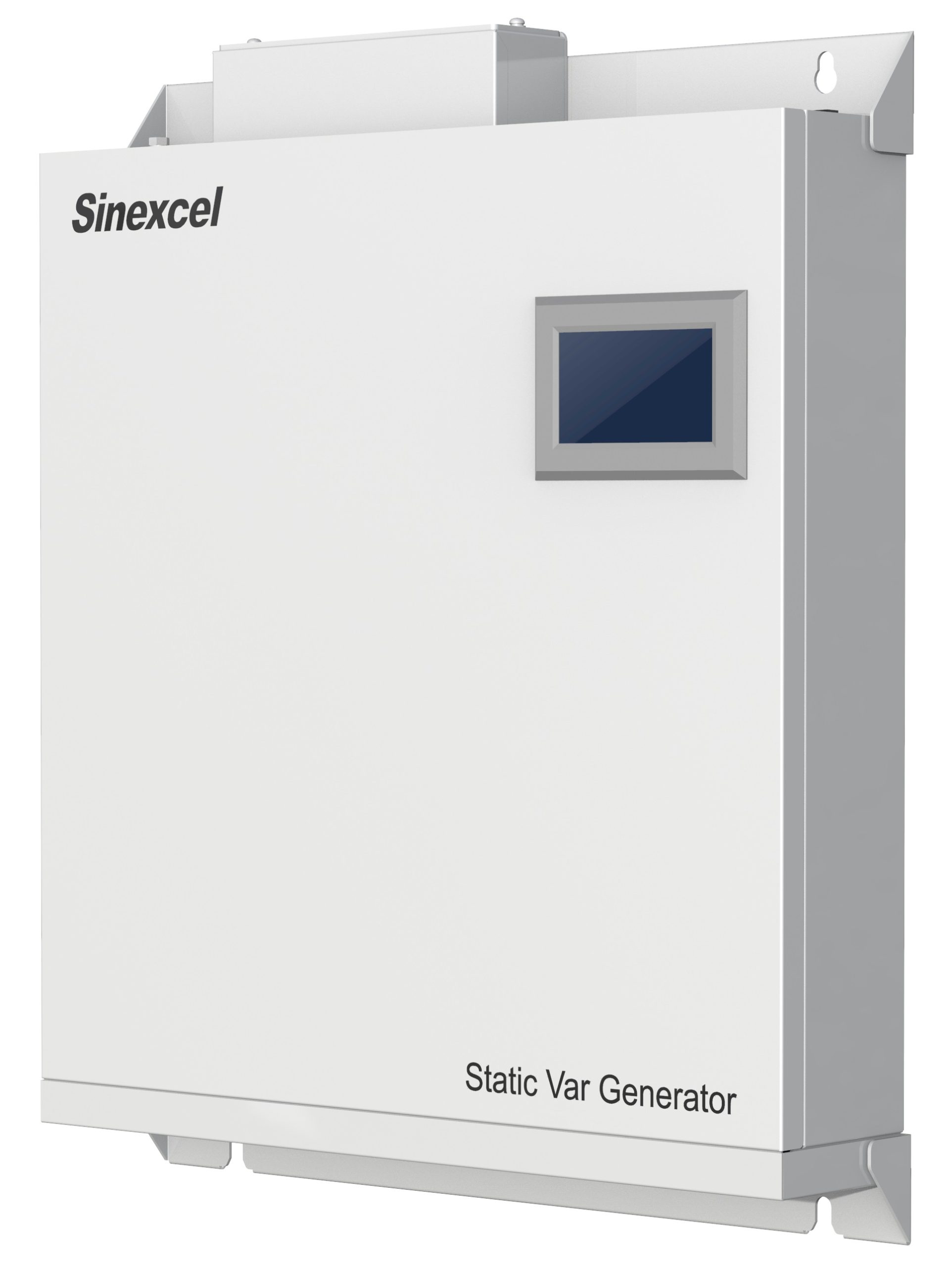
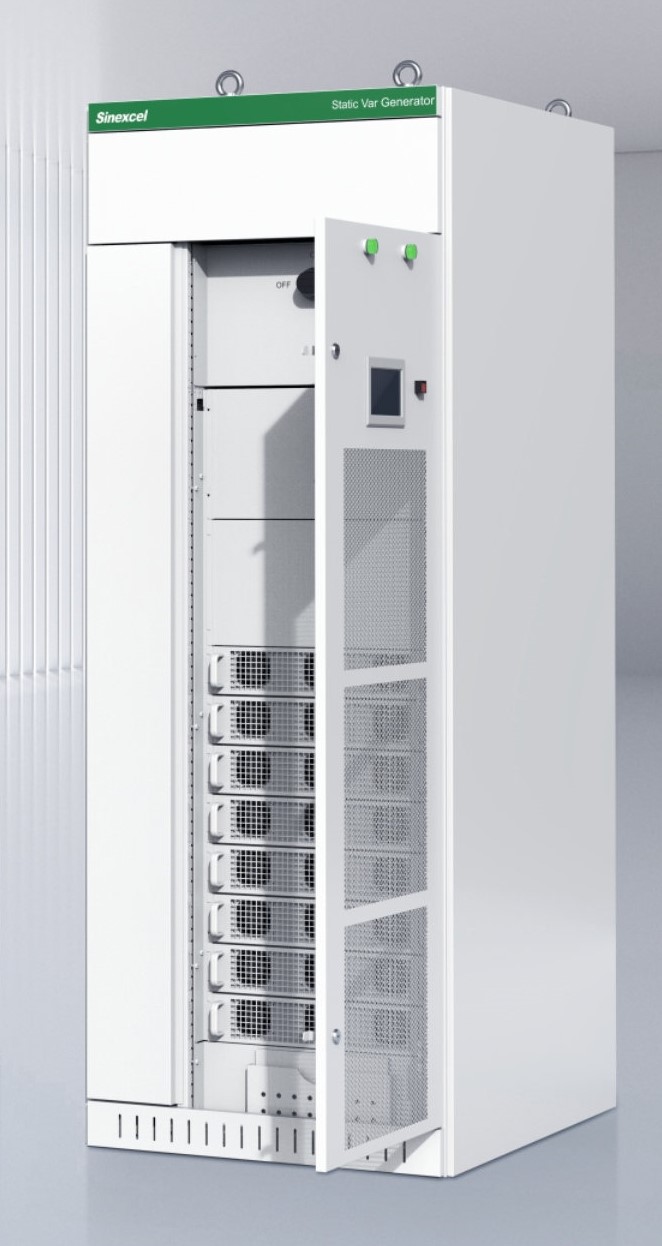
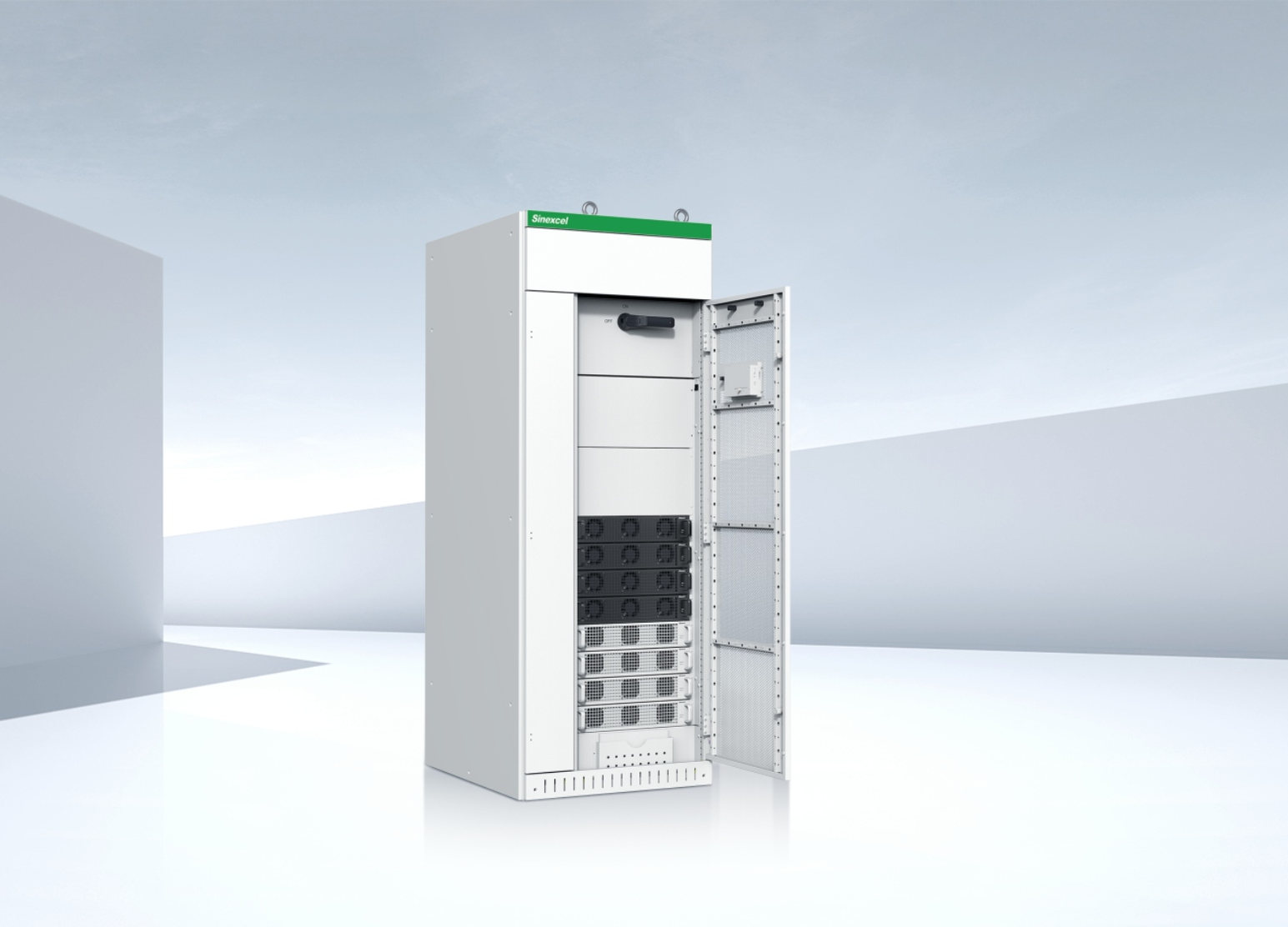
Wall mounted or panel mounted Ultra SiC SVG
Also available in rack mount and bookcase mounting
Ultra SiC SVG in space saving bookcase mounting.
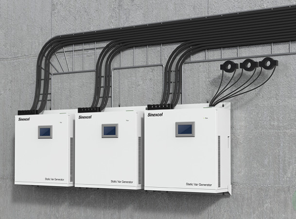
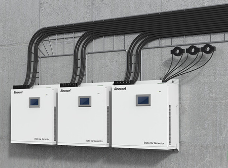
Example of wall mounting Ultra SiC SVGs (with CTs)
IP54 Ultra SVG with up to 1600kVAr of reactive power control
Example of a mix of Ultra SiC and Ultra SVG PFC
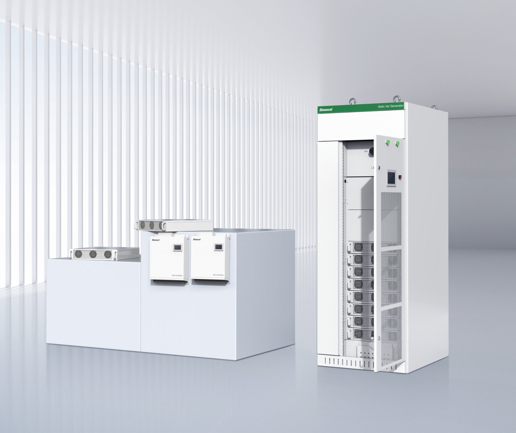
Ultra SVG with three mounting options.
Specifications:
220V to 415V Ultra SiC SVG specification
220V to 480V Ultra SiC SVG specification
NA Static VAR Generators
Presently Ultra SiC SVGs (and active filters) are only available to 480V. Above that voltage level another SVG range is available from 208V to 690V. For renewable applications the SVGs up to 800V are also available.
All NA models are suitable for wall and rack mounting in suitable enclosures.
208V-690V (800V for renewables) Wall/rack mounted
Rack mounted SVGs in dedicated enclosure
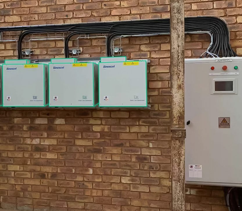
240kVAr (3 x 80kVAr) of wall mounted three level IGBT SVGs
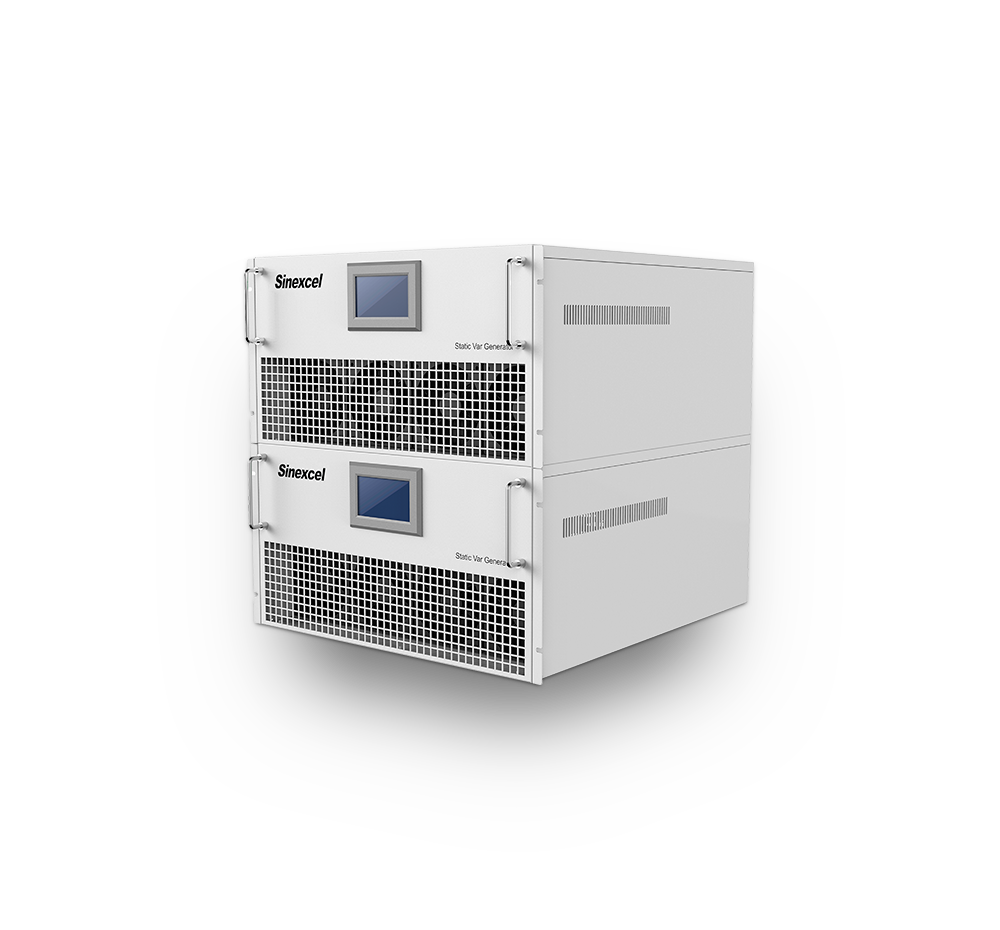
Example of two 50Kvar rack-mounted modules
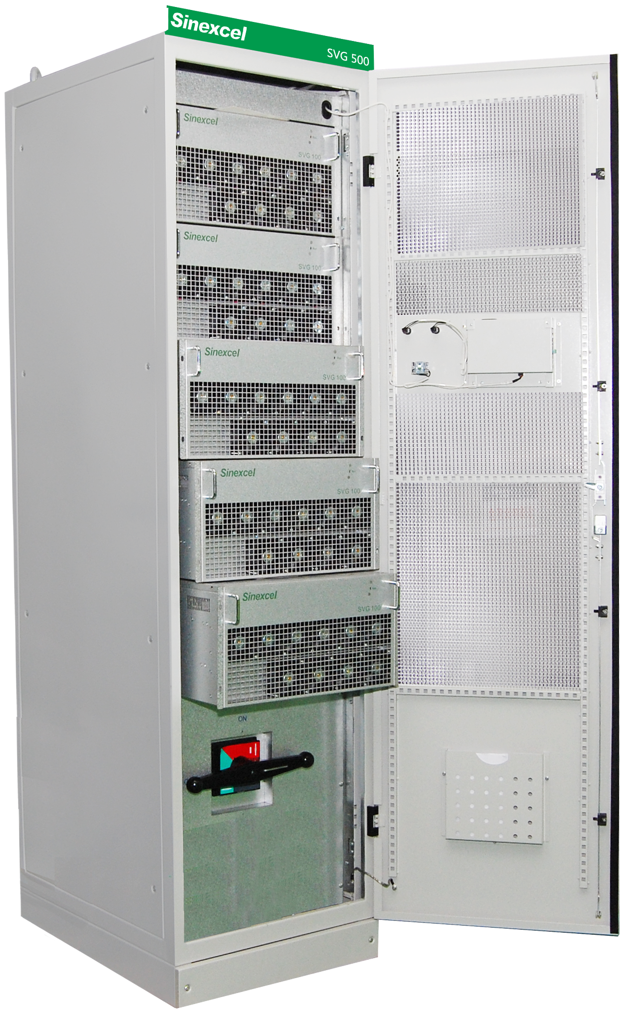
Rack mounted SVGs in dedicated enclosure
Specifications:
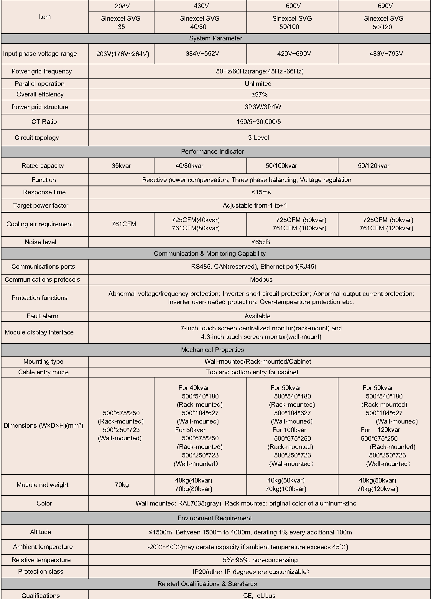
220V to 480V NA SiC SVG specification
For generator applications
Static VAR generators SVGs) can be used to compensate for lagging and leading displacement powers factors. Their speed of response is significantly faster than contactor or SCR based traditional capacitor-based PFC systems.
SVGs can be applied to utility-based power systems and generators. The typical generator capability curve is illustrated below. As can be observed, the generator’ unstable voltage region’ is clearly seen.
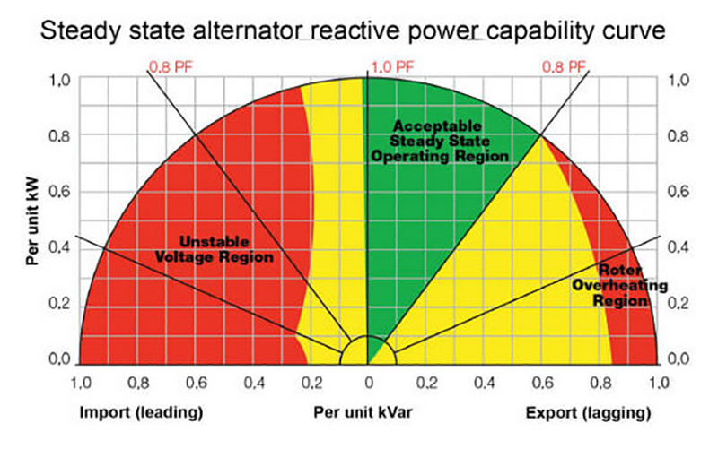
Typical generator compatibility curve. Note the unstable region due to leading DPF
Examples of where SVG can be used:
Example of ship (1 off 9 in class) with 3 x 2500kW AFE VFDs.
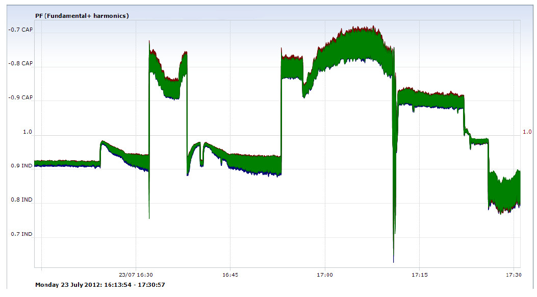
At no, light or intermittent load, DPF was unstable, toggling between 0.82 lag - 0.73 lead. This resulted in blackouts due to generator AVR tripping.
SVG would provide lagging VARs to compensate for leading DPF.
Generator based system with two manually controlled, passive harmonic filters/PFC. Leading DPF occurred when one or two filters not disconnected when system lightly loaded.
SVG would provide lagging VARs to compensate for leading DPF.
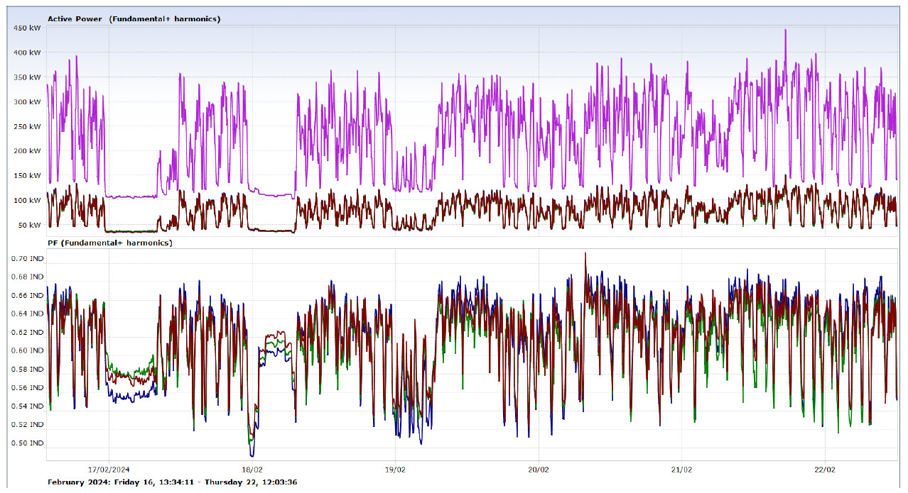
Factory subject to wide range of lagging and dynamic DPF. Passive PFC too slow to react effectively. SVG would provide leading VARs timeously to compensate leading DPF.
Data Centres are very important component within internet providers, financial sectors and other industries and, as such, require very high reliability of electrical power system. Data loss due to the supply voltage problems can be extremely expensive and embarrassing. UPS systems are therefore standard equipment in every data centre.
There are mainly two types of UPS. One is 50/60Hz UPS, the other is high frequency UPS, which are less expensive and more efficient than 50/60Hz types, and therefore, more popular However, this type of UPS can result in problems due to the electrical characteristics inherent in high frequency UPSs. High frequency UPSs result in leading DPF in the power system, which cannot be mitigated by conventional capacitor banks, which only compensate for lagging DPF.
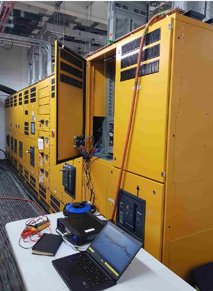
PQ testing in a large data centre in Ireland
High frequency UPSs utilise L-C filters in the input to minimise harmonic generation into grid during operation. The filter capacitors in the L-C filters generate capacitive reactive power to the grid when energised, resulting is a leading DPF in the UPS input, If there are only low values of UPS in the data centre the leading DPF will not be severe. However, if there large numbers of UPSs distributed around the system, the leading DPF will affect the complete data centre.
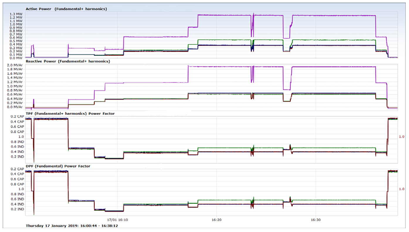
Example : True power factor (TPF) and displacement power factor (DPF) during system tests
Diesel generators are installed in all data centres for power system back in the event of failure of the utility and exhaustion of short-term UPS battery power. Diesel generators will only tolerate low amounts of leading reactive power (i.e. >0.9 leading DPF) before the AVR loses control and the generator(s) trip on overvoltage. In addition, the back-up generator(s) may not start in the first place if the leading DPF is too low, leading to total and catastrophic loss of power.
Sinexcel SVGs are ideal for data centres due to :
- 0.99-unity performance (or as programmed)
- Both capacitive and inductive(leading and lagging) load DPF compensation
- Step-less compensation, 15ms response time to changes for DPF
- No resonance or over/under compensation even on fast switching applications.
- No reaction to harmonics and will not generate harmonic
- Small physical SVG modules, 30 -200kVAr. Parallel up to higher powers.
- Wall, switchboard or panel mounting in complete systems (to IP54)
- Can be combined with Sinexcel AHFs on one connection and/or one enclosure
- Rating kVAr power is equal to compensation power
- Compensation reactive current not be reduced by voltage drop
300kVAr (3 x 100kVAr) wall mounted SVGs
SVG Brochures
Brochure : 220V to 415V Ultra SiC SVG
Brochure : 208V to 690V NA Ultra SiC SVG
Brochure : 220V to 480V Ultra SiC SVG

Sinexcel cabinet guide
Sentinel Power Quality has the knowledge and experience
Contact us with your application details and let us assist you.